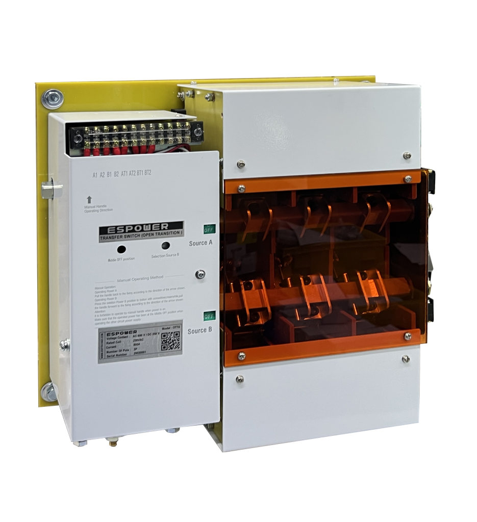
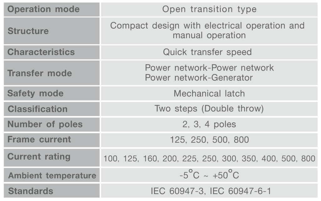
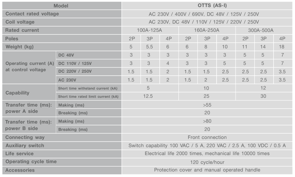
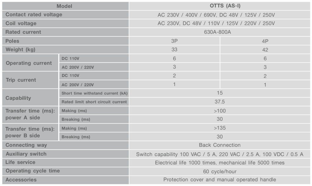
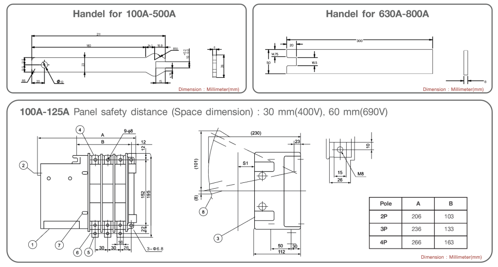
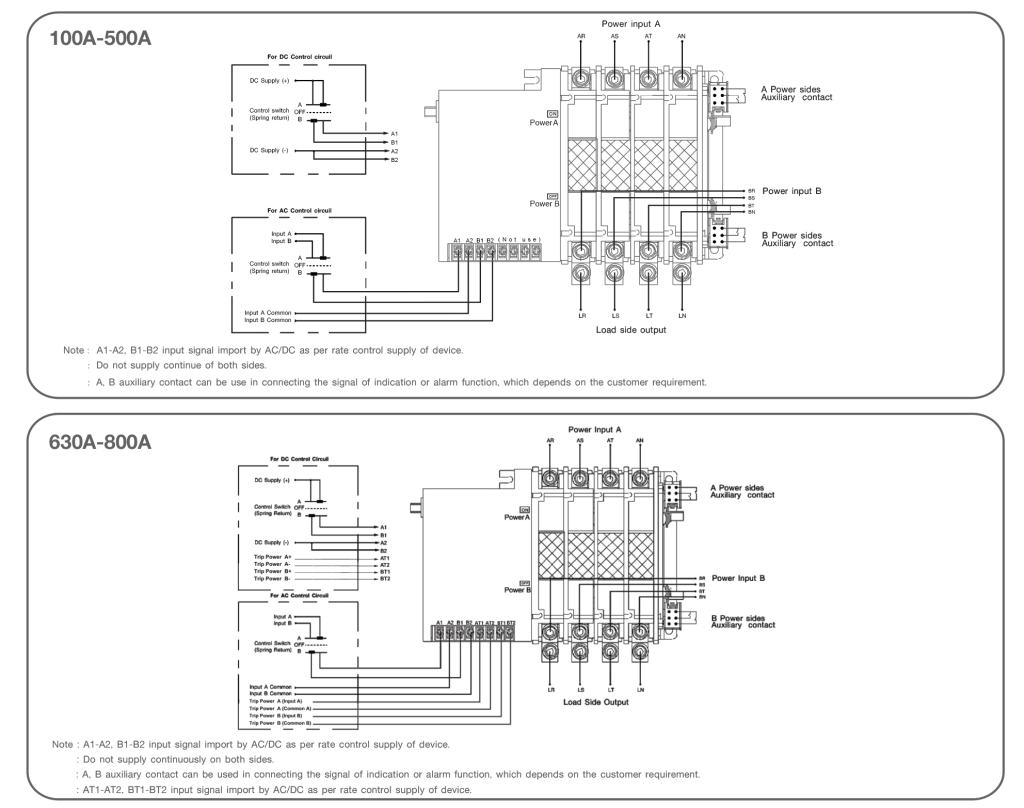
AUTOMATIC TRANSFER SWITCH

DESCRIPTION

      ATS series automatic transfer switch, is used in DC power system and AC power supply system with frequency of 50Hz/60Hz, rated working voltage is AC 690V or up to DC 250V, rated working current is 80 A up to 500 A. When one power supply fails, ATS switch to standby power supply automatically to ensure reliable power supply.

FEATURES

♦     Connection mode     

♦     Operation mode       

♦     Structure                   

♦     Characteristics             

♦     Conversion mode          

♦     Safety mode               

♦     Classification              

♦     Number of poles         

♦     Frame current             

♦     Current rating              

♦     Ambient temp.             

♦     Standards                     

: Front panel connection, back panel connection

: Open transition type   

: Compact design with electrical operation and manual operation 

: Quick transfer speed (transfer time is 0.1 – 0.2s) 

: Power network – power network, power network – generating network

: Mechanical latch 

: Two steps 

: 2, 3, 4 poles 

: 125, 250, 500 

: 80, 100, 125, 160, 200, 225, 250, 300, 350, 400, 500 

: −5°C ~ + 50°C 

: GB 14048.11, IEC60947-3, IEC60947-6-1 

♦     Connection mode   

♦     Operation mode   

♦     Structure        

♦     Characteristics    

♦     Conversion mode       

♦     Safety mode                

♦     Classification    

♦     Number of poles

♦     Frame current 

♦     Current rating  

♦     Ambient temp.

♦     Standards

: Front panel connection, back panel connection

: Open transition type

: Compact design with electrical operation and manual operation 

: Quick transfer speed (transfer time is 0.1 – 0.2s) 

: Power network – power network, power network – generating network

: Mechanical latch 

: Two steps 

: 2, 3, 4 poles 

: 125, 250, 500 

: 80, 100, 125, 160, 200, 225, 250, 300, 350, 400, 500 

: −5°C ~ + 50°C 

: GB 14048.11, IEC60947-3, IEC60947-6-1 

PRODUCT CODING

SPECIFICATION

DIMENSION

1)  Control circuit terminal

2)  Hand – operated handle entrance

3)  Auxiliary switch

4)  A Power side main terminal

5)  Main terminal load side

6)  B Power side main terminal

7)  ON/OFF position selector

8)  Hand – operated handle (Movable type)

CONTROL CIRCUIT DIAGRAM

ESPTECHNOLOGIES